Notifications
Clear all
Topic starter
06/12/2017 11:39:27
Webley Whiting.
With thanks to a collector friend for permission to photograph this extraordinary reproduction from the original plans by Mac Evans. This pistol never went into production.


Another Webley Whiting reproduction by Mac Evans:

Topic starter
06/12/2017 11:41:12
Webley Whiting Patent information.
With thanks to Peter for the patent information by Dennis Commins.

With thanks to John G for this pic:

Topic starter
06/12/2017 11:42:22
Webley Whiting Reproduction.
With thanks to the owner for permission to post these pics.


Topic starter
06/12/2017 11:43:41
Webley Whiting - Pair of Reproductions.
With thanks to the owner of these pistols, one of which is the same as the one pictured above.


Topic starter
06/12/2017 11:47:31
Webley-Whiting - Yet another reproduction build.
Courtesy of Leonardj.
Originally posted in 2015.
Earlier this year, John Griffiths began a thread over on the Airgun BBS which documented his building of a Webley-Whiting air pistol. I followed his thread with great interest, and as his project progressed, I found myself inspired to build my own rendition of this unique and rare air pistol. The 1910 Webley-Whiting was to have been Webley's first air pistol, but for reasons unknown, only one prototype was ever made by Webley. Those who have built replicas of the gun speculate that the relative complexity of the design, along with it's inability to provide adequate acceptable velocities due to the limitations of it's powerplant, were the major contributing factors for the decision to not proceed in producing it commercially.
John also kindly put me in touch with a couple other individuals that had built their own replicas of the pistol, and between the three of them, a great deal of information was provided to assist in my build. Many thanks to John, Tom, and Mac for the drawings, pictures, and for sharing your experiences of your own builds.
As with any journey, it all begins with the first step, and this picture pretty much illustrates that point. A scaled up copy of the original 1910 patent drawings, and four blocks of steel to begin the four major components of the gun - the frame, the compression chamber, the piston, and the rear end plug.

Appropriately sized holes are drilled in the locations that result in the required radius at key points on the frame. The excess material is then bandsawed away.

The edges are then milled to size, and the thickness of both the upper portion of the frame, as well as the grip area of the frame are cut to the proper width.


The steel for the compression chamber is then set up in the lathe, and that long, rather small compression chamber is bored. The threads for the rear end plug are also cut. As can be seen in the second picture below, there is not a lot of "wiggle room" when machining this piece.

The inletting for the sear and piston lug access are then milled into the underside of the compression chamber, and it is then fitted to the main frame.

The one piece piston is machined to size, and the sear engagement groove has been cut.

The cocking link lugs are then milled to size, the radius cut on the leading and trailing edges, and the hole for the cocking link engagement pin drilled.

The piston skirt opposite the cocking link lugs is then cut to size. Just a matter of setting up in the lathe to bore the hole in the piston, and it will be done.

The piston is then fitted to the compression chamber so that it moves freely, but with no excess slop.

The compression chamber is then fitted to the lower frame, and the hinge bolt hole is drilled, tapped and counterbored for the fastening screw. The inletting for the trigger mechanism and cocking link operation has already been milled into the lower frame.


I went with a one-piece rear plug, spring guide, and rear sight arangement. The relief radius for the action hinge has to be cut into the underside of the threaded portion, and the rear sight has to have a few finishing touches done as well.

I managed to find a suitable candidate for the barrel in my stash of barrel cut-offs - a length of Walther barrel with a 17 mm OD (0.6693"). The breech end was cut to size, threaded, and the shoulder for the breech seal cut. The muzzle end was then crowned.

An improvised drive dog is made up to fit the thread on the breech, and the taper is cut using the offset tailstock method. The barrel is 0.500" OD at the muzzle.

The finished barrel is trial fitted to the frame, and all looks good.

The gun is really taking shape.

A quick rummage through my wood scraps was rewarded with a very nice piece of black walnut, large enough to produce a pair of grip blanks, with enough left over to allow for my learning how to checker, and to allow for me to practice that skill on the very same wood used for the grips.

The radius has been cut on the top of the compression chamber, the dimples on the sides for grasping the compression chamber for cocking have been cut, the hole for the compression chamber latch mechanism finished, and the holes drilled for the trigger component fixing pins. The machining marks have been polished out on the sides of the frame and the compression chamber, but there is still much polishing of other detail areas to do. The grip blanks have been fitted for the pics.


Next items to machine are the more fiddly little bits - the trigger parts, the sear, the compression chamber latch parts, the cocking link, the trigger guard, and the front sight.
The sear was the first of the small parts to be made.
In this pic, the sear has been fitted to the compression chamber, and is engaged with the piston in the cocked position. The small set-screw was a small refinement that I added, to allow adjustment of the sear engagement.

Next, the trigger assembly was fabricated. This consists of four parts - the trigger, the intermediate sear bar, a small tensioning spring for the intermediate sear bar, and a short pin to hold the assembly together.


The cocking link was then fitted. It has to lay against the back of the trigger's intermediate sear bar, at just the right height to be able to engage the piston for cocking, yet fall away from the piston as the compression chamber is closed for firing. This pic shows the cocking link at a point where the sear has just engaged the piston.

The trigger guard was then machined, cold formed on a mandrel, and cut to length where it meets the grip. Once the trigger guard has been fitted and it's fastening pin driven into the frame, the trigger guard is then milled to it's finihed width of 7/16". A ball end cutter is used to form a fillet at each point where the trigger guard meets the frame.


Now it was time to tackle the latch mechanism. Having received prior warning that this little detail could be the cause of some frustration, I took my time and managed to get a working latch on the first try - but - while it worked just fine, I was not satisfied with it. A second iteration of the parts was made, making adjustments to the areas that I was not happy with, and the result was a smooth operating latch mechanism, with no slop or over-travel.


I chose to go with a press-fit plug to fill the front of the latch mechanism hole, rather than to fit a screw. Once the face of the plug has been blended with the front face of the frame, the plug becomes pretty much invisible, and effectively mimics the blind hole shown on the 1910 patent drawings.

Last but not least, the fitting of the front sight.
I chose to go with a press fit of the front sight element into the barrel slot, which resulted in a clean looking, and solid assembly.

The gun has been tested for funtionality, and everything is working great.
Still much left to do though:
- harden those parts that require it.
- fit the proper, full power mainspring.
- disassemble and polish out all the machining marks.
- engrave the appropriate markings into the side of the compression chamber.
- bluing.
- checkering and finishing of the grips.

After a much-too-long break from working on this project, I finally got back to it.
One of the hurdles that I ran into was how to go about applying the "Webley & Scott Ltd." markings on the side of the compression chamber. I do not have access to a pantograph, and not one of the many local trophy engravers were willing to even try cutting lettering in steel - even if I supplied the needed cutters. I was hesitant to try using an etching process due to my unfamiliarity with the chemicals and the process itself. That left the option of perhaps purchasing a set of 1/16" letter stamps with a gang punch capable of doing each line of text in one blow, but after pricing them, that idea was dropped. That left but two options open to me - try buying a set of individual 1/16" letter punches and trying not to make a mess stamping one letter at a time, or just forgo the markings on the gun, and perhaps print the details on the lid of the storage box I intend to build for the gun. I decided on the latter.
The next obstacle I ran into was the bluing. I had hoped to have the gun hot-salts blued, but was unable to locate any shop locally that was willing to do the job. I also wasn't too keen on shipping the gun to some shop whose best estimate on turn-around time was "whenever we get enough guns to make a run worth while". As a result, I reluctantly decided to try bluing the gun myself using one of the cold blue formulas available.
The cold blue job finished up nicer than I had expected, but not as nice as I would have liked.


You will notice as well, that the grips have not yet been checkered. I am not yet satisfied with my checkering skills, and will not tackle these grips until I am confident that I will be able to do a job that I will be happy with.
Testing and Performance:
The mainspring that I chose for my build is the center spring from the two spring set found in the Anschutz LG380, cut down to 37 coils. Initial testing with this mainspring was very encouraging, resulting in a ten shot average velocity of 299.24 FPS with JSB RS pellets (7.33 gr), for a muzzle energy of 1.46 FPE. The gun was then disassembled for bluing.
During re-assembly after the bluing, I burnished moly paste into certain key areas, in addition to the light oil that I had used in my earlier, initial test. The piston seemed to slide much smoother than before, so I was wondering if any improvement might be realized in the gun's performance. After a few test shots to allow things to work in a bit, it was time to run a few shots over the chrony.
Once again, I was pleasantly surprized.
Using JSB RS pellets (7.33 gr), a ten shot average of 312.84 FPS was recorded, for a muzzle energy of 1.59 FPE. I decided to try some heavier pellets to see what the results might be.
Using JSB Exact Express pellets (7.9 gr), the ten shot average was 304.42 FPS, for a muzzle energy of 1.63 FPE.
Next, I tried the JSB Exact pellets (8.44 gr), and recorded a ten shot average of 293.35 FPS, and 1.61 FPE muzzle energy.
Due to the length of the barrel, the pistol is muzzle heavy, and this imbalance is exacerbated during the shot cycle, making the gun a bit of a challenge to shoot well. After plenty of practice shots, I decided to try shooting some targets.
The first target was shot at 5 yards, using the JSB RS pellets, from a standing, offfhand position, using a two hand hold. I was able to keep 10 shots within about a one inch +/- group, with the best of the targets shot at this distance measuring 0.937" CTC.

Next, I tried shooting a few targets at 10 yards, using the same pellets and shooting position as before. Well, I don't know if I was just tiring, or if it was because my poor old eyes were having difficulties with focusing on the targets and sight picture at the increased distance, or what, but the 10 shot groups were now averaging around three inches, with the best target of the bunch measuring 2.687" CTC.

All-in-all, a very enjoyable project, with a satisfying outcome, and an excellent addition to my Webley collection.
Topic starter
26/11/2018 17:17:54
Webley Whiting-type air pistols
With thanks to John G for posting these pics on the BBS, which were given to him courtesy of a German collector friend. He said:
"Unfortunately there is not much information to go on. Both pistols are apparently Czech in origin, but have no markings, and as they came from two completely different sources they do not seem to be related. The first pistol, which has its rear sight missing, looks like a manufactured product and given its rarity if it was retailed it would have been only for a short time. The second pistol resides in a Czech museum and is most probably a prototype. The name “Brno” is written on its museum label , so the gun could have been made by the same company that makes Slavia airguns.
"Interestingly some thought has gone into overcoming a few of the problems of the basic Whiting design. For example, both pistols have the cylinder pivot pin located farther forward compared to the Whiting, and so the cylinder can be pulled back much further in a larger arc than the Whiting when cocking. This makes for a longer piston stroke and so presumably more power. The cylinders, being wider, also provide a bigger swept volume, and equally important, give you something much more positive to grip when cocking the gun...
"There was a gap of at least 70 years between the registering of Whiting’s patent and the appearance of these two versions of his design. The Webley Whiting patent was “lost” for many years as it was believed to have been taken out in 1911, and searches for that year turned nothing up. It was not until 1979 that Dennis Commins discovered the patent, and found that it was actually registered in 1910. He published his findings in Guns Review that year, so most probably these two versions of the Whiting were made some time after 1979."


31/05/2022 23:57:10
My Interpretation of a Webley-Whiting: Success or Failure?
By Pierre, (R-Gun Pete), as posted to the Canadian Airgun Forum
In this first part, I will start by an overview of where I am starting from.
I retired a few years ago and, after having been a graphic artist (at the beginning of my career) then being recycled as a technical draftsman/CAD expert somewhere in the middle and adding CNC milling operator to the mix for the last twenty years of my working life, I thought I would revert to more artistic activities.
In my first year of retirement, I did a whole bunch of drawings (portraits and others) and discovered that even if I was still extremely good at it, the old passion was not there. I guess that I was missing designing and machining stuff.
This is when we were hit by the pandemic and forced to stay at home. As travelling was not an option anymore, it freed up a bit of money and after coming across some mini lathe at a reasonable price, I decided to make the jump and setup a small workshop in my garage.
So, in the Fall of 2020, I got acquainted with turning which was a bit alien for me as all my previous machining experience had been strictly CNC milling. I enjoyed making round parts for a short period, but I was missing machining flat plates.
In less than a month the devil tempted me again and by mid-November of 2020 a mini mill was sitting beside the mini lathe. By then I just had time to try the mill a few times before it was getting snowy then the cars were back in the garage.
In 2021, from early Spring to late Fall, I made a lot of accessories for my lathe and my mill and started to get confidence in what I was able to do manually with both machines. I also worked on some projects related to my replica airguns and decided to make wooden holsters for my Luger, my Mauser Broomhandle and my Browning HiPower. The attachment clips to use the wooden holsters as shoulder stock were machined from aluminum.

I also made a shoulder stock interpretation for my Colt SAA.

One of my friends had broken the indexing lever of his Daisy 853 and I thought that it would be a good challenge to see if I could make one for him. The part was very small and needed to be cut at different angles, so I decided to carve it from a larger plate. One side is not pretty because I couldn’t machine a sloped surface and had to file it down by hand. To my surprise, he dropped it in his rifle, and it worked.

The end of the season was approaching as I came across that post on the forum. I thought that it was very interesting and would give me some work to do in my CAD program over the winter months.
It was about a Webley Whiting replica made by one of our members, Leonardj, based on the patent drawings of a 1910 prototype that was never commercially built.
This is the link:
https://forum.vintageairgunsgallery.com/webley-pistols/webley-whiting/#post-178
This post sent me to another one where I discovered all the steps used to build his pistol very well documented. It also seems that a couple of other persons, one in England and one in New Zealand, tackled the same project and their pictures were also very useful.
It is possible to see a video of the Webley Whiting replica in action as well as some others with this link:
[See also: https://forum.vintageairgunsgallery.com/webley-pistols/webley-whiting/#post-177 ]
Part 2
This second part is about the virtual reconstruction of a 3D model.
Based on the patent drawings I found in the previous links I mentioned and, on the information that I extracted from the Webley Air Pistols book, I was able to scale up the picture to bring it to the actual size of the original to use as a template.
In Adobe Illustrator, I made a first 2D geometric construction that looked like that. The square at the bottom is my 1-inch reference for when the file was brought in SolidWorks.

After the 3D model was built, I started to look at how I could build it. I have a limited selection of stock, drill bits, taps, springs and cutters.
This is a 2D drawing of the 3D model.

Because both my machines are mini, I knew that the model I would attempt to built will be an interpretation on the theme of the Webley Whiting and not a reproduction as the other peoples did.
My first step was to find a suitable spring in my box. I thought I had a good candidate that seems to have a good stiffness and an OD of 3/8” but was a fair bit short. I proceeded to stretch it to about 4 ½ inches.
This would dictate that my piston would be hollowed to 3/8” from a ½” brass bar and that the aluminum cylinder casing (Upper Receiver) would be drilled ½” for the piston to fit in.
The original model has both the Upper and Lower Receiver the same width and needed a set of dimples to be able to cock it. In my case, the largest piece of aluminum available dictate that I should use a ¼ “ plate and make the Lower Receiver in two mirrored halves for a total of ½”. Consequently, the Upper being larger than the Lower the dimples were not necessary.
This is the 2D drawing of the components inspired by the Webley Whiting.

Part 3
I started making the base parts using the band saw to rough both halves of the Lower Receiver then clamped them together to drill the holes for the location pins and holding screws. From that point they were treated as single unit to clean most of the edges on the mill with the tight spots finished off with files and a Dremel tool.
The barrel and the piston were done on the lathe and the front sight plus the piston hook were a bit of a hack job.
The outside of the Upper Receiver was milled to size and drilling the ½” bore proved to be a challenge due to the space and limitation of my machines. The lathe couldn’t be used because I only have a three jaws chuck. The mill didn’t have enough clearance to have the Upper Receiver in a vertical position and the drill chuck with the ½” drill installed. Starting the hole on the drill press was not an option either because I couldn’t ensure that it would be perpendicular.
So basically, I had to start on the milling machine with a ½” endmill in a collet, the big aluminum block in my vise and the top of the Upper Receiver as close as possible to the top surface of the big block. I went as far as I could with it, then after removing the Receiver/block/clamps assembly, switched the endmill to the ½” drill still using the collet and I had to slide back the assembly on the drill. It was not an ideal situation because the drill was already engaged in the hole and since it was difficult clearing the chips, the drill tip was binding and causing the mill to stop.
The picture below (on the left) shows the arrangement for the drill press, in this case the bottom of the Upper Receiver was flush with the bottom of the block. Even then, the maximum space between the tip of the drill and the adjustable table was barely enough to accommodate the Upper Receiver. Completing the hole to the right depth was a bit painful as the travel of the drilling head was not enough. This meant that the drill had to be started engaged in the hole and after a few pecks completely retracted by lowering the table, this process being repeated until the depth was reached.
On the right, some of the basic parts are shown. Unfortunately, the spring I had chosen for the project didn’t fit. The OD was .370” on both ends but, when I stretched it to the length I wanted, some spots grew between .380” and .390” and couldn’t slide in my piston. In fact even at .370” I am not even sure it would have fit my 3/8“ piston cavity when compressed. I ended up making a new spring from welding wire.

The next picture shows some details of the cuts in the Upper Receiver, the sear, the piston with the hook pinned to it, the spring guide that needed to be done twice because I broke the first one when I tried to cut the 9/16-12 thread with a die by holding it by the small shaft of the guide rod and the home-made spring. There is no need to say that the second time I cut the thread BEFORE making the small shaft.

Finally, this picture shows the components of the Lower Receiver. Both halves of the Lower receiver are pointing in the same direction so the inside and outside can be seen. On the right side, starting from the bottom, there are the trigger guard, the under-barrel lug that attaches to the latch plunger and spring, the barrel, and the front sight. On the left side, from the top, there are the cocking link, the trigger/trigger lever assembly, and the trigger spring. The latching system to lock the Upper Receiver has been changed from the original model drawings to my version because I didn’t have enough room.

Part 4
Having a whole bunch of scattered part is not enough as they must work together. This meant multiple assembly/disassembly to check fits and functions.
The Sear has been done twice. The first one worked perfectly when I was just holding it in place with my thumb. It was snapping in place when the piston was retracted and releasing the piston when I was pushing on the tail of the sear. I screwed up when I drill the pivot hole for the sear in the Upper Receiver. It was too close to the edge in relation to the depth of the cutout recess for the sear. After talking to a friend, I followed his suggestion not to mess with the Upper Receiver and to redo another Sear. This time I made it slightly thicker and drilled the Sear pivot hole, in the cocked position, using the Receiver hole as guide. After that I was able to machine the Sear slanted surfaces that provided the clearance.
My 3D model was functioning perfectly but my actual parts being made on very basic manual machines without digital readout had appreciably looser tolerances than their virtual counterparts.
The other part I had to do twice was the trigger lever. That is the part pushing on the tail of the sear to release it. Cut to the size of the drawing, the nose didn’t have enough meat. The problem was rectified on the second one.
The next step was to solve my pins problem to prevent them from falling and the project was nearly finished.
To complete the pistol, I made a set of wrap-around wooden grip.
This picture shows the result from different angles.

I mentioned that I had to scale down the size of the pistol compared to the original. The picture below shows some proportion.

Mechanically, the pistol works well. Pulling on the Under-Barrel lug unlatches the Upper Receiver. When the Upper receiver is pivoted up the Cocking Link engages the Piston Hook and pulls it back until the Sear snaps in the Piston groove. Returning the Upper Receiver to its original position allow the Cocking Link to Fall back in the Lower Receiver and after it is latched, it is ready to fire. Pulling the trigger releases the piston with a satisfying “CLINK”.
The picture shows the Cocking Link doing its job.

Now you will ask me the million dollars question. Does it shoot???
All this fiddling around was done with the piston without the o-ring installed because it was easier to make all the adjustments to the parts and assembly.
I will tell you that I was also curious to see how it would perform. So, I installed the o-ring, put some pellgun oil on it as well as in the chamber, and slid it in. It seemed to be a nice fit and I thought that it would compress. I reinstalled the Spring and the Spring Guide in the Upper Receiver and reassembled it to the Lower Receiver.
Now the moment of truth. Unlatch, Cock, Relatch, Pull the Trigger.
What a downer!!! A mouse’s sneeze would be stronger.
Maybe my original spring might have been better that the one I made from the .035” welding wire but I don’t have enough meat to enlarge the bore in the piston, so I don’t know.
Consequently, unless I can make another stiffer spring that fits, I will have to be satisfied with a pistol that make a nice “CLINK” (I have removed the o-ring as the mouse’s sneeze was too depressing).
It is a bit disappointing but, on the other hand, I am glad of what I was able to achieve with my hobbyist’s machines.
My verdict would be a successful failure.
First Part of the New Version: Compression Chamber
Following the hints given in Leonardj’s reply, I decided to try improving the compression of air.
As I was happy with my successful failure, I didn't want to modify my first version. My intent was to keep the Lower Receiver and to make another complete Upper Receiver to achieve a result where the piston slides inside the compression chamber and seals without an o-ring.
To do so I had to use a completely different strategy than what I did for my first version.
Before I continue, I want to briefly review my main machinery equipment to explain the kind of limitations I was facing. I have a hobbyist’s plain jane mini-lathe and mini-mill as well as a basic small drill press.
The following picture shows how much room is left once a half-inch drill bit is installed in the mill, the lathe and the drill press.

The other restriction I imposed on myself is to use material that I have in my shop. For round bars I have a selection of ½, ¾ and 1 inch. My lathe chuck can probably open to 1 1/8” before I need to switch to the other set of jaws and until now 1 inch was all I needed. For flat plates or bars, I have a bunch of bit and pieces of different thickness.
Also, the spring that I had selected for my initial project was nominally 3/8” but didn’t fit in the cavity of my first piston after it was drilled with a 3/8” bit. I discovered that it was in fact .390” so, for the new version, the piston hole will be enlarged to accommodate it. I was not sure if it would be strong enough and one of my friends told me he could send a piece of a M14 recoil spring that actually measures .375” in diameter.
Having set my new goals, I started to think how to achieve them. Knowing how difficult it has been to drill 4 1/2” deep for my first version of the compression chamber, I opted to do it on the lathe this time around. I also wanted to keep the drilling to a maximum of 2 1/2“ deep which would require making it in 2 parts.
When looking at the patent drawings it is easy to see that the compression chamber is located above the centerline of the Upper Receiver. Ideally, starting with a 1 ¼” diameter bar I could have squared it up after drilling the hole and obtained the same relative position as shown on the drawing. Unfortunately, this couldn’t be achieved using a 1-inch round bar and made my life slightly more complicated.
This picture shows the drawings for the modified parts. They are more or less dimensioned because sometimes I directly glue the paper to the part for machining.

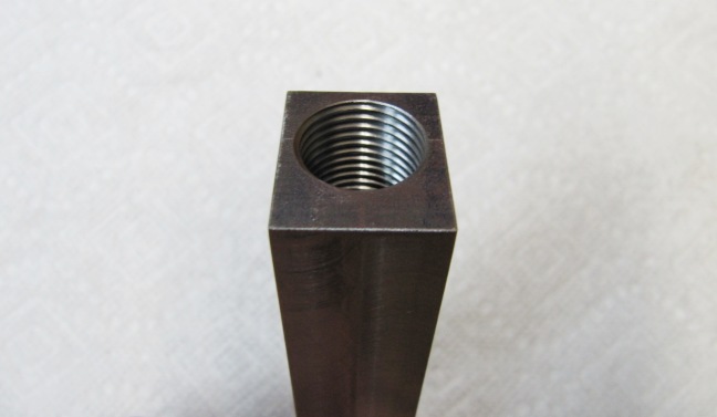
My first task was to make all the round parts on the lathe (2 pieces for the compression chamber, a test plug and the piston). It should have been relatively easy but even that proved to be challenging.
I have a fairly good set of letter, number and fractional drills and the idea was to drill smaller than 1/2'” to get as close as possible to that value in order to remove the least possible amount of material from the piston to get a good fit.
Easier said than done. I started my first half from a 1-inch aluminum round bar and after using my smaller than ½” drill (31/64”) the hole ended up slightly oversize and the actual value was .510”. Luckily this half could be used for the end of the piston with the hook and I redid the process with another piece of aluminum but this time drilled in increment starting with 3/8” and going up in size slowly.
What is annoying is that the lathe tailstock has about only 1 5/8” of travel meaning that it must be retracted, moved into the hole and the motor started again in order to drill deeper. I was drilling 15/32” when I forgot to retract the drill chuck before moving it deeper in the part to go the depth I wanted. Guess what ?... Not good… I reached the end of the screw, the drill chuck got free and spun with the part in which the drill was engaged and pull it out of the lathe chuck jaws.
Other than having a few gouges on the outside of the round bar nothing was broken. After removing the drill from the hole to measure the bore, I discovered that I was still within the size I needed to reach. I reinstalled the piece in the jaws using undamaged surface areas and drilled with the 31/64”. This time I was closer to .485 and that was OK since I wanted to adjust the fit when machining my piston. At this point, all that was left was to drill the transfer port in the compression chamber half and cut the 9/16 – 12 thread in the other.
Before even thinking of touching my brass bar, I experimented with an aluminum plug to find the size I needed to obtain the desired fit. Since I don’t have reamers, I sanded the inside of the bore with a wood dowel covered in sandpaper to make it smooth and slowly increase the diameter to .490 comparing the bore to my plug by trying to slide it in. Once I had a better idea of what I was doing I machined the outside of the brass piston.
Then I was back to drilling (again), this time the depth was 2.1” so, technically, the same procedure of moving the tailstock as before. I thought to use the same incremental approach to drill the hole for the spring cavity. The plan was to start with a 3/8” bit then finish it with a letter W drill. I never had problem machining brass on the CNC mill since the feed and speed is precisely set and there is a lot of flood coolant. I was in for a surprise. It seems that brass work hardens and when I started with the W drill, thinking that it should be easy since I had to remove only a few thousands of an inch, it completely jammed in the piece. I am not sure if I was trying to feed too quickly but to remove it was fairly time consuming. Once I got it out, I still needed to complete the operation and I was able to finish it without binding the drill again.
The good news was that my original spring now fitted in the piston, the bad news was that I discovered that some cracks were made when the drill jammed in the part.
The picture below shows both halves of the compression chamber, the aluminum plug, the brass piston and the sanding dowel. There is also a closeup of the cracks in the piston mouth.

Second Part of the New Version: Milling of the Compression Chamber and the Sides
To continue making the Upper Receiver, I moved to the mini-mill.
Both halves of the compression chamber must be assembled to become a single unit. I did it by using the tongue and groove method.
The idea was to make sure that the side containing the compression chamber was long enough to provide a seamless surface, for the sealing surface of the nose of the piston, then a tongue would be left to fit in the groove of the rear half.
I started by cutting the groove with a ¼” endmill in the rear half (opposite to the end which will have the 9/16-12 thread for the Spring Guide) and, on the compression chamber half (opposite to the transfer port), I made the tongue with such a tolerance as to provide a locational fit in order to assemble both halves.
At this point I knew that the tolerance between the piston and the compression chamber should be good, but I didn’t have the chance to really test it. Now that the cut gave me access to the back of the piston, I could pull and push on it with my fingers. With the transfer port open the piston slides freely but when it is blocked by a finger, letting the piston go down by gravity, it falls very slowly and when pulled quickly out it makes a popping sound. I think it is promising.
The picture below shows different views of both halves and the piston.

It is just the beginning to look like the Webley Whiting Upper Receiver, a lot more work is coming.
First, both halves assembled as a single cylinder must be machined lengthwise to become a rectangular prism having a square cross-section and each side should measure exactly .700”. The tongue must also be parallel to the top and bottom faces and perpendicular to both sides. To ensure that nothing would move the test plug was inserted to provide a bridge between both halves.
This picture shows the four steps to transform the Compression Chamber from a cylinder to a square bar.

To achieve the proper positioning of the axis of the Compression Chamber and to look like the required Upper Receiver, two sides must be machined one the mirror image of the other. The bottom will be thicker to provide some room for the sear and must touch the other side. The top will have just a small overhang to grab the top of the squared cylinder.
In order to be able to assemble the four components a small cut .063 deep and .108 wide must be made lengthwise on both top and bottom corners of the squared Compression Chamber.
I think this will be easier to understand with the following picture.

Third Part of the New Version: Assembly of the Upper Receiver
To transform those four components into a single Upper Receiver, they must be mechanically fastened together. The plan was to pin them but, as there is practically no room to manoeuver, all the holes had to be precisely located. At other locations, like some holes on the Lower Receiver, I drilled 1/16” holes but I was getting wary of those small bits because they tend to break at the most inopportune moment.
Since I had to go fairly deep in relation to the diameter of the drill, I opted to go one size bigger and use a 5/64” drill bit. Six holes were required (three on each side) with a pair located in the middle and going through the tongue and groove, another at the front (close to the transfer port), and the last pair at the back (in front of the thread). These pins going from top to bottom are passing through, from the narrow top ledge to the thicker bottom plate of the side plates, locking the square body of the compression vessel in place. Basically, it would have been possible to disassemble the Upper Receiver at any time in the future if I had not broken a drill bit in hole number 5. It is now permanent.
I added another locking feature at the lower front portion, by threading a hole for a 6-32 screw, which had its counterpart at the back (provided by the pivot pin attaching the Upper Receiver to the Lower Receiver).
After the Upper Receiver was successfully transformed into a single part, I discovered that I had a major problem that needed to be solved before being able to continue. If you remember, at the beginning of Part 2 of the New Version, there was an aluminum plug that was inserted in the bore of the cylinder to keep it aligned when it got squared. It was still there and didn’t want to come out. If you also remember I broke a drill bit in one of the pin holes, so impossible to disassemble either. My only option was to try to push it through the transfer port (5/64” in diameter). I had a finishing nail that fitted in the hole and I was able to make the plug move a little bit but it was way too short.
I started looking everywhere in my shop and everything I found was either too small (I didn’t want it to bend and to scratch the inside of the compression chamber) or too big (I didn’t want to enlarge my transfer port). At some point I came across a brass coat hanger which was the perfect size. By cutting it different lengths, I was able to keep it as stiff as possible and by using these pieces in succession I was finally able to push the plug out. Another hour wasted.
To complete the Upper Receiver the recesses for the Sear and the groove for the Piston Hook were milled. Since its final dimensions were slightly different (and also because I didn’t want to touch my original) a new Sear was made.
The picture below shows the Upper Receiver before and after assembly and machining as well as the New Sear.

My new Piston was ready but the new hook was not made yet. In the first iteration the ring of the Piston Hook was a sliding fit and required the addition of a pin through both parts to mechanically locked them together. This time I wanted to have an interference fit.
If you remember, the mouth of the Piston cavity has been cracked after the binding of the drill and was flaring out a bit. In order for it to engage the ring of the hook I needed to squeeze it slightly inward. As it was probably work hardened, I was afraid that it could break. I don’t have a blow torch so I asked a friend to help me with the annealing.
After making a small jig to control the squeezing of the cracked region, I was able to make it start to slide in the ring of the Piston Hook. Encouraged by that, I though that if the Piston was placed in the freezer and the Piston Hook was heated up with a heat gun I should be able to get an interference fit.
The next picture shows the Piston and the Piston Hook before and after assembly.

The only thing missing to have a fully working Upper Receiver was the Spring Guide.
I knew that the Spring Guide had given me some problem the first time and it happened again, but for a different reason this time. Having learned my lesson, the 9/16-12 thread was not an issue for the new one, but it seems that I had forgotten that the notch for the Lower Receiver should be the last operation (after the small shaft was cut). This time I cut the notch BEFORE turning down the small shaft. That was a mistake that made my life miserable because, even with the dead center in the tail stock to hold the threaded portion in line, that missing chunk was creating a lot of vibrations. The result was that it took me probably more than twice as long as it should have been to bring down the small shaft to the right size.
Eventually it was done, as you can see on this picture of the Upper Receiver components.

After checking that the piston was still sliding slowly in the compression chamber when the transfer port was blocked, I started doing some test with the spring installed.
At the beginning, it was very stiff because the spring must completely disappear inside the piston cavity for the Sear to engage the cocking ridge on the Piston head and the few last coils were rubbing on the mouth of the Piston.
This took a bit of time to solve and in the meanwhile I discovered that the interference fit between the Piston and Piston Hook was not as strong as I thought it would be. With all that moving around it became a close sliding fit.
This meant another phone call to my friend. After a quick meeting with the blow torch and some plumbing solder I was now back in business. This time the joint between both parts was not going anywhere.
Fourth Part of the New Version: Completing the Pistol Assembly
Even after all the tests with the Upper Receiver, I was still not sure if I was heading toward success or another failure. A new piece of masking on the transfer port was not blown away when releasing the piston under spring tension. The same test done with an older (less sticky) piece seemed to work but nevertheless it was a bit depressing. On the other hand, the system was still dry so, maybe, some lubrication would change the outcome.
There is a snapshot sequence from my video clip.

I encountered another delay when I tried to assemble the pistol. Due to the slight increase in the dimensions of the new components of the Upper Receiver, the Piston Hook ended up located a bit further closer to the pivot pin when the Piston head reached the cocked position. It was also moving a bit further forward when fired.
This required a new Cocking Link and some changes to the channel for the Piston Hook as well as a slight enlargement of the cavity for the Cocking Link in the Lower Receiver Assembly. It meant a disassembly that I would have preferred to avoid and some extra milling to both halves of the Lower Body. This also meant a few extra scratches on my finished parts.
Now the stress was building up, the moment of truth was approaching and I was bracing for another failure. I disassembled again the Upper Assembly (hoping it would be the last time). I carefully greased the Piston Hook channel in the Lower Receiver as well as the Cocking Link then I applied some grease on the Spring, Spring Guide, Piston Hook and Piston body but not the head. The head was covered with Pellgun oil and also the inside of the compression chamber too. By hand, I worked out the piston back and forth then blocked the transfer port with my finger and it seemed that I was getting some suction/compression but I had no clue if it would be enough.
I attached the cocked Upper to the Lower Receiver because, otherwise, it would not be possible to engage the small hook of the Cocking Lever, then I dried fire the pistol. It didn’t sound very promising but again there was no resistance.
Now it was really the moment of truth. All system were Go and once I pulled out the barrel underlug to unlock the Upper Receiver I was beginning my first try. I didn’t even have the front nor the rear sight installed on it, but it didn’t matter since I would be shooting point blank.
Pulling up on the Upper Receiver, I could see that the Cocking Lever was engaged in the Piston Hook and was doing its job. I continued until the Sear clicked in place and the pistol was cocked. I placed a pellet in the breech, closed the Upper Receiver, locked it and aimed at the old, battered pop can that I had placed in my pellet trap.
I pulled the trigger and to my stupefaction I heard “KERPLINK” and the pop can fell.
I couldn’t believe it…!!! It worked…
There is a snapshot sequence from my video clip.

That night, I continued to shoot several times and discovered that the pistol was sensitive to pellet sizes. If they were just a tiny bit too large the pistol would choke on it. I made a little gauge Go/No Go style and it solve my problem. If they were small enough to slide through, they were a perfect fit for my barrel.
The next morning, I was sure that I was home free. I only had to complete the machining of my Rear and Front Sights (which went well) and to drill a small hole for a 4-40 screw thread in my Spring Guide (which shouldn’t be very difficult). I was so wrong to think that because everything went to hell.
I thought that I had drilled and tapped deep enough for the screw I had planned to use. It was a flat head and it sort of work but because the wall thickness of the rear sight was on the thin side, I didn’t want to countersink it. My first mistake was to think that I could easily switch from one type to another. The flat head was tightly holding the rear sight in place but it was because the base of the cone was pushing on the edge of the drilled hole. A 4-40 x ½” flat head screw is not exactly the same as a ½” round head because in this case the head is not included in the measurement. The result was that the round head screw bottomed out before applying pressure on my rear sight.
What do you think I did? Yes the stupid one, that’s the thing I did.
Instead of looking for a shorter screw, I thought it is only aluminum so I could get one or two more turns. WRONG… The screw broke a few threads under the head and the balance was below the surface and into my hole. That’s what happened.
What should have been a few minutes job to complete the installation of the Rear Sight on the airgun turned out to be a lot more time consuming. After an hour, trying to cut a slot in the end of the beheaded screw with a hack saw then with a Dremel tool using different types of attachments, the only result I was achieving was mangling both the screw and the hole. In frustration, I stopped for lunch and ,as we were eating, my wife told me to check with my friend if he would have some suggestions. It turned out that it was a great idea because my friend had a screw extractor that would be perfect for screws ranging from #3 to #6. A short walk, a bit of drilling and a little bit more fiddling with the screw extractor and I was back in business.
No need to say that this time the screw was the right size and was treated with respect. The use of a couple of washers helped too.
Now that the air pistol was completed and functional, I decided to make a little video to show Leonardj that his suggestions had been very helpful. After shooting several dozen of pellets through it, I could see that it was not an armor piercing weapon but I was just happy that it worked.
For my previous test I had used an old battered pop can that was already full of holes but for Leonardj’s demonstration I started with a new one. Since the pellet was denting the aluminum but not piercing it, I guessed that this air pistol would about in the same range as the low velocity spring airsoft guns.
Following is a snapshot sequence from the video showing the cocking, loading, locking and shooting the air pistol.

Fifth Part of the New Version: Conclusion
I liked very much the look of my original first version with the chamfered top edges but I can live with the squarish look of the new one and in fact, when checking pictures of Webley semi-autos, my this version would easily fit with them.
The picture below shows different angles of the pistol with the new version of the Upper Receiver.

After getting in touch with Leonardj to show him the video, he told me that it might be interesting to Chrony my project to see what kind of velocity is obtained with the short barrel version that I made.
I knew that it was not very powerful nevertheless I was able to tumble the pop can from 15 feet. It is true that at that distance I was hitting and missing about equally so, finally, I discovered that 12 feet gave me the most consistent results where practically all the shots were “hits”. I also discovered that when the air pistol was freshly oiled it seems to hit a bit harder.
For the velocity tests, I didn’t want to spatter oil droplets into my Chrony sensors. As I already had a shooting session the day before, I left it as it was and after getting ten pellets through my Go/No Go gauge I was ready to start.
What a surprise. When I saw the results, I realized my nice working “all built from scratch” air pistol was probably at the level to compete with pea shooters.
Those are the numbers in fps: 87.02 – 87.43 – 76.89 – 89.16- 77.26 – 78.57 – 89.05 – 82.53 – 83.72 – 72.58.
I remembered that I own an old Webley Junior (I think it is from 1935) that I had rebuilt several years ago. I made a new leather cup seal for it as well as machining a new piston screw to hold it (the original screw was broken). After the repair it has been functional but always low powered. I thought it would be a good comparison velocity test.
So, these are the numbers for the Webley Junior (again in fps): 175.9 – 159.9 – 150.4 – 174.2 – 170.7 – 176.9 – 162.3 – 168.1 – 168.1 – 173.9.
Since I was in comparison mode, I also remembered that I have an old Crosman Walther P99 6mm BB airsoft from before the 1998 ban. Those plastic pistols are amazing, I got it out and it was working perfectly. These are the numbers I got for the airsoft (in fps): 152.9 – 150.2 – 148.7 – 149.5 – 147.9 – 149.0 – 153.4 – 150.7 – 154.2 – 148.5 – 155.0.
At this point, I thought that I might as well shoot a couple of targets from 12 feet to check what kind of pattern I would get from my short unrifled barrel.
The picture shows the pistol with the small gauge, the pellets I used for the test and both targets with 10 shots each.

The project was completed and I wanted something nice to keep it in. I found this box, which was the perfect size, so I just needed to cut some shapes in a sheet of Masonite then covered it with a piece of stretchy fabric. The addition of the drawings glued in the cover made the finishing touch and this the result.

|
In conclusion, I must say that I am glad to have been encouraged to persevere because even if I was happy enough with my first iteration (my successful failure), it is very satisfying to actually be able to shoot an air pistol based on a design more than 110 years old. From a machining perspective, this second version brought me a different set of challenges and combined with what I learn with my first version, it was a very educative project. Cheers. R-Gun Pete
|
